|
欧姆龙mg电子老虎机官方入口的一部分型号在数据上已经超过其它同类品牌的mg电子老虎机官方入口产品,产品质量已经达到行业领先地位。 OMRONmg电子老虎机官方入口(MOSFET)优势特点:产品无触点,因此没有触点的消损,产品使用寿命延长;防震,抗抖动;体积小,依... 微机测控系统中,经常要用到功率接口电路,以便于驱动各种类型的负载,如直流伺服电机、步进电机、各种电磁阀等。这种接口电路一般具有带负载能力强、输出电流大、工作电压高的特点。南方先进电子mg电子老虎机官方入口产品APV210A替换AQW210A产品,产... mg电子老虎机官方入口,亦称光电阻隔器或光电耦合器,简称光耦。它是以光为前言来传输电信号的器件,一般mg电子老虎机官方入口只能传输数字(开关)信号,不适宜传输模拟信号。近年来问世的线性mg电子老虎机老虎机可以传输连续改变的模拟电压或模拟电流信号,使其应用领域迅速拓展。 产... 开关电源的光耦主要是隔离、供给反应信号和开关作用。开关电源电路中光耦的电源是从高频变压器次级电压供给的,当输出电压低于稳压管电压是给信号光耦接通,加大占空比,使得输出电压升高;反之则关断光耦减小占空比,使得输出电压下降。旦高频变压器次级... 关于PLC控制器供电的电源,应选用非动力线路供电,直接从低压配电室的主母线上选用专用线供电。选用隔绝变压器,且变压器容量应比实际需要大1.2~1.5倍左右,还可在隔绝变压器前加入滤波器。关于变送器和共用信号表面供电应挑选分布电容小、选用... 欧姆龙品牌开发了一种新型的绝对压力传感器,它是一种绝对压力传感器,可以精确检测高度差的压力变化。 绝对压力传感器采用了欧姆龙核心技术之一的MEMS技术,以达到世界最高水平的高精度和低电流消耗。 欧姆龙绝对mg电子老虎机官方入口的应用领域包括室内导... mg电子老虎机官方入口属于固态继电器,普通电磁继电器靠电流经过线圈使铁芯变成有磁性的磁铁吸合衔铁,从而使相关的触点动作控制负载的通断,而mg电子老虎机官方入口没有触点,其工作原理与光耦有点相似,用mg电子老虎机官方入口就是固态继电器,用光耦驱动可控硅,控制光耦端给适宜 Product line up
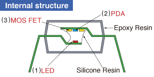
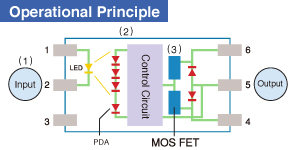
A PhotoRelays is a semiconductor relay with an LED as an input and MOSFET as an output.
|
|
Compared with Electro-Mechanical Relays
have moving contact: |
Compared with SSR (Solid State Relays) have phototriac for output: |
|---|---|
|
●Longer lifetime (No limit on mechanical and electrical lifetime) ●Higher-speed and high-frequency switching ●Higher sensitivity (less power consumption) ●Smaller size ●Less contact problems such as arcs, bounce, and noise ●More resistant to vibration and impact ●No limitation for the mounting direction |
●Able to control miniature analog signal ●Applicable to both AC/DC ●More sensibility ●Less leakage current ●Lower offset voltage ●Various contact structures such as 2a, 4a, 1b, 2b, and 1a1b in addition to 1a |
1.Technical Terminology
2.Reliability tests
|
Term
|
Symbol
|
Description
|
|
|
Input
|
LED forward current
|
I
F
|
Current that flows between the input terminals when the input diode is forward biased.
|
|
|
LED reverse voltage
|
V
R
|
Reverse breakdown voltage between the input terminals.
|
|
|
Peak forward current
|
I
FP
|
Maximum instantaneous value of the forward current.
|
|
|
LED operate current
|
I
Fon
|
Current when the output switches on (by increasing the LED current) with a designated supply voltage and load connected between the output terminals.
|
|
|
LED turn off current
|
I
Foff
|
Current when the output switches off (by decreasing the LED current) after operating the device with a designated supply voltage and load connected between the output terminals.
|
|
|
LED dropout voltage
|
V
F
|
Dropout voltage between the input terminals due to forward current.
|
|
|
Power dissipation
|
P
in
|
Allowable power dissipation between the input terminals.
|
|
Output
|
Load voltage
|
V
L
|
Supply voltage range at the output used to normally operate the PhotoRelays.
Represents the peak value for AC voltages.
|
|
|
Continuous load current
|
I
L
|
Maximum current value that flows continuously between the output terminals of the PhotoRelays under designated ambient temperature conditions. Represents the peak value for AC current.
|
|
|
On resistance
|
R
on
|
Obtained using the equation below from dropout voltage V
DS
(on) between the output terminals (when a designated LED current is made to flow through the input terminals and the designated load current through the output terminals.) R on = V DS (on)/I L |
|
|
Off state leakage current
|
I
Leak
|
Current flowing to the output when a designated supply voltage is applied between the output terminals with no LED current flow.
|
|
|
Power dissipation
|
P
out
|
Allowable power dissipation between the output terminals.
|
|
|
Open-circuit output voltage
|
V
oc
|
Voltage required for driving a MOSFET
|
|
|
Short-circuit current
|
I
sc
|
Current that is output from the driver when the input is turned on
|
|
Electrical
characteristics
|
Turn on time
|
T
on
|
Delay time until the output switches on after a designated LED current is made to flow through the input terminals.
|
|
|
Turn off time
|
T
off
|
Delay time until the output switches off after the designated LED current flowing through the input terminals is cut off.
|
|
|
I/O capacitance
|
C
iso
|
Capacitance between the input and output terminals.
|
|
|
Output capacitance
|
C
out
|
Capacitance between output terminals when LED current does not flow.
|
|
|
I/O isolation resistance
|
R
iso
|
Resistance between terminals (input and output) when a specified voltage is applied between the input and output terminals.
|
|
|
Total power dissipation
|
P
T
|
Allowable power dissipation in the entire circuit between the input and output terminals.
|
|
|
I/O isolation voltage
|
V
iso
|
Critical value before dielectric breakdown occurs, when a high voltage is applied for 1 minute between the same terminals where the I/O isolation resistance is measured.
|
|
Ambient
temperature
|
Operating
|
T
opr
|
Ambient temperature range in which the PhotoRelays can operate normally with a designated load current conditions.
|
|
|
Storage
|
T
stg
|
Ambient temperature range in which the PhotoRelays can be stored without applying voltage.
|
|
Max. operating frequency
|
—
|
|
Max. operating frequency at which a PhotoRelays can operate normally when applying the specified pulse input to the input terminal |
|
Classification
|
Item
|
Condition
|
Purpose
|
|
Life tests
|
High temperature storage test
|
T
stg
(Max.) |
Determines resistance to long term storage at high temperature.
|
|
|
Low temperature storage test
|
T
stg
(Min.) |
Determines resistance to long term storage at low temperature.
|
|
|
High temperature and high humidity storage test
|
85°C
185°F , 85%R.H. |
Determines resistance to long term storage at high temperature and high humidity.
|
|
|
Continuous operation life test
|
V
L
= Max., I L = Max., I F = Recommended LED forward current |
Determines resistance to electrical stress (voltage and current).
|
|
Thermal
environment
tests
|
Temperature cycling test
|
Low storage temperature (T
stg
Min.) High storage temperature (T stg Max.) |
Determines resistance to exposure to both low temperatures and high temperatures.
|
|
|
Thermal shock test
|
Low temperature (0°C)
(32°F) , High temperature (100°C) (212°F) |
Determines resistance to exposure to sudden changes in temperature.
|
|
|
Solder burning resistance
|
260±5°C
500±41°F , 10 s |
Determines resistance to thermal stress occurring while soldering.
|
|
Mechanical
environment
tests
|
Vibration test
|
196 m/s
2
{20 G}, 100 to 2,000 Hz*1 |
Determines the resistance to vibration sustained during shipment or operation.
|
|
|
Shock test
|
9,800 m/s
2
{1,000 G} 0.5 ms*2; 4,900 m/s 2 {500 G} 1 ms |
Determines the mechanical and structural resistance to shock.
|
|
|
Terminal strength test
|
Determined from terminal shape and cross section
|
Determines the resistance to external force on the terminals of the PhotoRelays mounted on the PC board while wiring or operating.
|
|
|
Solderability
|
245°C
473°F 3 s (with soldering flux) |
Evaluates the solderability of the terminals.
|

mg电子老虎机官方入口 是固态继电器的一种。英文是Solid State Optronics Relay。
一般继电器都是机械触点,靠通电流过线圈变成有磁性的磁铁吸合触点,从而控制开光状态。而mg电子老虎机官方入口工作原理类似于光耦,是由微电子电路,分立电子器件,电力电子功率器件组成的无触点开关。用隔离器件实现了控制端与负载端的隔离。固态继电器的输入端用微小的控制信号,达到直接驱动大电流负载。mg电子老虎机官方入口归于 固态继电器 ,一般电磁继电器靠电流经过线圈使铁芯变成有磁性的磁铁吸合衔铁,从而使相关的触点动作操控负载的通断,而mg电子老虎机官方入口没有触点,其工作原理与光耦有点类似。mg电子老虎机官方入口为AC/DC并用的半导体继电器,指发光器件和受光器件一体化的器件。输入侧和输出侧电气性绝缘,但信号可以通过光信号传输。其内部的发光二极管是用来向光电元件放射光线的,光电元件接受光线并控制输出场效应管导通或截止。mg电子老虎机官方入口还有另一种可控硅整流管(SCR)输出,它的负载电流比场效应管更大,后者可达到数安培,而前者可达到几十安培。相对于电磁继电器,mg电子老虎机官方入口由于没有触点引起的磨损,使用寿命是无限的,同时也具有无震动、无切换声音等特性,与电磁继电器一样可控制各种负载(灯泡、发光二极管、加热器、马达等)。
mg电子老虎机官方入口有无机械触点,长寿命,低动作电流,高隔离电压,高速切换。低泄漏电流,交直流兼用。广泛用于测量仪器,通讯设备,办公自动化。在选用继电器时,最重要的指标是所选继电器的触点电流和电压,以及控制继电器导通开断的信号的电流和电压大小。在使用时,小功率的继电器一般直接焊接在电路板上,中大功率的继电器一般会安装在继电器座上,依据需要冉将继电器座安装在标准导轨上。由于继电器容易产生火花,因此在较大的功率的时候,建议考虑使用固态继电器、交流接触器等。通信用继电器将在今后继续增长,占到全球继电器市场的1/4。高频继电器是其发展的主要方向,在电信领域、无线通信、宽带输送接入等需求的推动下,已成为机电式继电器更新换代的新平台和下一代通信技术加速完善的助推器。体积更小,适用于表面装贴,高可靠,抗干扰性能优良的通信继电器需求旺盛;未来5G发展所需用的新型通信继电器将成为其发展主流。第四代通信继电器技术已日渐成熟,第三代移动通信的展开,为其提供良好的市场前景。光继电器/微电子继电器是电子产品向数字化、自动化、超小型化方向发展所必需的。
光继电器/微电子继电器由于其泄露率小、隔离性能好、输出特性稳定优良等优点,其应用领域在不断扩大。适用于“物联网”的光继电器由于其高灵敏性、高可靠性而成为优选产品,将会是下一代继电器发展的重要方向。